Tube Drawing
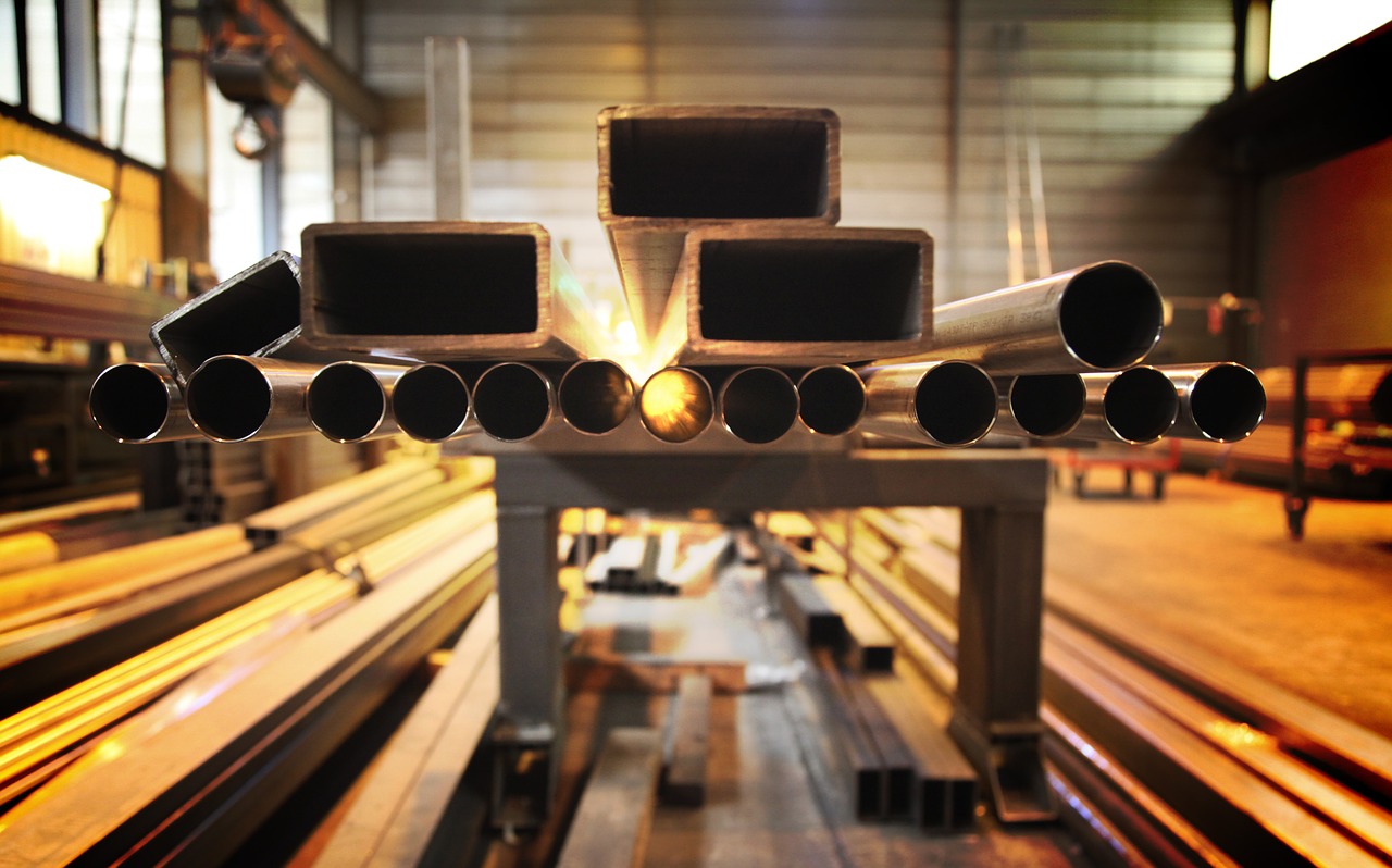
Tubes are an integral part of the modern world and are present in almost every industry. They are used mainly for transferring pressurized or unpressurized fluids (liquid and gas) but also for structural purposes.
As such, tubes find use in various industries, including construction, aircraft, oil, gas, petrochemical, automotive, chemical, water treatment, sanitary systems, medical, pharmaceutical, etc.
This variety also necessitates tubes with various inner diameters (IDs), outer diameters (ODs), wall thicknesses, and materials used (View our Tube Sizing Chart). Moreover, some industries need tubing with variable diameters from one end to another.
This brings us to custom tubing and tube drawing. This method is widely used for creating metal or alloy tubing with various diameters and wall thicknesses. It also increases the strength and hardness of the final product thanks to cold working. Let’s take a deeper look.
What is Tube Drawing?
Shortly, tube drawing is a cold-working process that changes the outer and inner diameter of the tube and its wall thickness by drawing it through a die or a series of dies.
Tube drawing also refines the internal grain structure, improving the mechanical quality of the drawn tube. Moreover, tube drawing can achieve precise dimensional tolerances and improve the surface finish.
Various tube drawing methods are utilized, depending on the quality required, tubing length, and material used. These include sinking, rod drawing, fixed plug drawing, floating plug drawing, and tethered plug drawing.
Tube Sinking
Tube sinking is the most common and basic drawing process, also known as simple tube drawing.
Unlike other processes, tube sinking doesn’t utilize internal tooling (mandrel) or support, and as such, it can’t change the wall thickness significantly – only the outer and inner diameters. Moreover, tube sinking produces tubes with worse surface finish quality, though it does reduce cost significantly.
That said, the wall thickness can change according to the die angle used. To keep the wall thickness, one should use a 24-degree angle. Meanwhile, higher angles can thin out the tube wall, whereas lower angles will make it thicker. Still, due to the limitations of this process, it can produce tubing with uneven wall thickness.
Tube sinking can produce tubing of satisfiable quality for applications that don’t demand a lot of precision. Still, it is often used as the first step of diameter reduction, followed by more precise methods.
Rod Drawing
Unlike tube sinking, rod drawing incorporates a mandrel that moves with the tube. The presence of the mandrel helps maintain the integrity of the inner diameter. It also prevents the tube from collapsing while also allowing for a more significant reduction in diameter compared to tube sinking. As a result, this process is quicker and produces tubing with a better surface finish.
Crucially, rod drawing produces tubes with much more precise internal diameters; as such, it is commonly used in high-precision applications, including medical tubing and aerospace hydraulic systems.
Nonetheless, rod drawing has disadvantages regarding the length of the tubes since the length of the mandrel affects the length of the tube. In practice, one can produce tubes up to 100 feet (30 meters) in length.
Fixed Plug Drawing
Fixed plug drawing combines elements of tube sinking and rod drawing. Therefore, it allows for precise control over the tube’s external and internal diameter. In this process, the mandrel sits stationary and doesn’t move with the tube. The mandrel is part of the die assembly and supports the internal surface during the process.
This process can’t produce long tubes thanks to the stationary plug, but it is the best one for achieving a higher surface finish. In addition, fixed plug drawing allows for extremely tight dimension tolerances, making it an excellent choice for precision tubing applications in the automotive, aerospace, and medical industries.
The biggest disadvantage of fixed plug drawing is that it is a slow process, though it can be used for significant reductions in the cross-sectional area.
Floating Plug Drawing
Floating plug drawing incorporates a mandrel that floats within the tube throughout the drawing process and is held in place through friction forces. The plug is positioned a short distance from the die entrance and is usually tapered for better wall thickness control.
This process produces tubing of very good wall thickness uniformity, but crucially, it can manufacture very long tubes measuring over 1,000 feet (300 meters) long. Therefore, it is mainly used in the oil and gas industry, like down-hole oil exploration.
Floating plug drawing requires adequate lubrication and material purity to be successful, though it does produce tubing with a smooth internal finish.
Tethered Plug Drawing
Tethered plug drawing is a process where the mandrel floats, just like in a floating plug drawing, but also anchored via a tether, just like in a fixed plug drawing. You won’t be mistaken if you view it as a mix of the two. This method produces long, straight tubes and a higher-quality inner surface finish than rod drawing.
This setup allows the plug to maintain an optimal position inside the tube as it’s drawn through the die, offering enhanced control over the internal diameter and wall thickness. Moreover, tethered plug drawing produces tubing with a better internal surface finish, making it an excellent choice for hydraulic systems.
Tandem Drawing
Tandem drawing is accepted as a standalone process in the metalworking industry, though it’s a combination of two or more tube drawing processes. Notably, in this process, one would align several dies and plugs in a series, thus allowing the tube to pass through multiple drawing stages. Each stage reduces the tube’s diameter and wall thickness and enhances the strength and surface finish.
Although more complex than other processes, tandem drawing can produce tubing of superior quality. Moreover, it allows the production of long, small-diameter tubes with exceptional wall thickness uniformity and consistency. As such, it finds use in the electronics and telecommunications sectors and other high-performance applications.
Materials Used in Tube Drawing
Tube drawing is mainly used for producing metal tubes from different alloys. It is mainly used for producing stainless steel and carbon steel tubing but also copper, aluminum, nickel, and titanium alloys.
The material selection depends on the required mechanical properties, corrosion resistance, and the tube’s intended use. For instance, stainless steel tubing is used in applications that require excellent corrosion resistance, like medical devices, aerospace, automotive, and architectural applications. Carbon steel tubes, meanwhile, provide excellent strength and hardness and find use in cars and industrial machinery.
Copper and its alloys are also widely used in tube drawing processes thanks to its excellent ductility and thermal/electrical conductivity. Copper tubing is widely used in HVAC systems, plumbing, and electrical applications.
Meanwhile, aluminum alloys are used in the aerospace and automotive industries thanks to the excellent strength-to-weight ratio of these alloys. Aluminum tubing is also widely used for producing stiff and lightweight bicycles.
Lately, Titanium has had a resurgence. Although hard to work with and weld, it emerged as a popular option in the bicycle industry. Titanium tubes are lighter and stiffer than aluminum ones but are much harder and more impact-resistant. In addition, Titanium is used for producing medical implants, thanks to the human body’s acceptance of the element.
Tube drawing can also be used for Nickel-alloy tubes, which have exceptional corrosion resistance. As such, these tubes are widely used in the chemical industry. Some specialty alloys, like Inconel, Monel, and Hastelloy, provide even higher corrosion resistance and strength. As a result, these alloys are widely used in chemical processing plants, oil and gas extraction, and aerospace components.